Search

Showing posts with label heat transfer experiment. Show all posts

Reboilers operation, design aspects and applications

Well, a boiler is equipment used to convert liquid into high-pressure vapor. It is familiarly known as the famous equipment "steam boiler", that produces steam from water. However, a reboiler does the same operation, due to its involvement in the continuous process of boiling the recycling liquid stream in its shell side. The name was given by the reason for boiling the same liquid again and again. In most cases, the liquid is boiled in a shell with the help of hot pipes (tubes). On the external surface of the tubes, liquid changes its phase by observing heat (latent heat + sensible heat). In turn, the required high temperature of the hot tubes is maintained by circulating low-pressure or high-pressure steam inside the tubes. Based on the temperature sensitivity of the material and rate of vapour formation boiling is done inside or outside of the tubes. 

Types of reboilers:

  • Kettle reboiler (natural-circulation)
  • Thermosiphon reboiler (natural-circulation, operates based on the head of liquid) Calculators
    • Vertical model
    • Horizontal model
  • Forced circulation type (liquid is pumped into the shell)

Applications: 

Used as heating equipment for distillation column (generates vapors for the bottom tray like Glycol reboiler, Amine reboiler, etc).
Steam production using hot process streams.

Reboiler design aspects: 

Designing a shell-type reboiler for the required process conditions involves making a decision about the basic options before starting the design calculations. An engineer with his experience can choose the type of flow in and outside of the tube, using plain or finned-type tubes during the primary selection of the model. He even considers the reboiler cleaning frequency, and how to minimize the startup time. Nucleate pool boiling data, knowledge of two-phase flow theory, and heat transfer coefficients are some of the important information required for designing.

To improve the performance of heat transfer rate, low-temperature approach enhanced boiling tubes are used in new models which benefits the industrial economy. 

Variables that influence the reboiler design are: 
  • Pressure drop (pressure gradient)
  • Mass velocity
  • Flow pattern (parallel, cross, counter types)
  • Tubes orientation (vertical or horizontal)
  • Critical heat flux condition
  • Thermal hydraulics
  •  Reboiler duty
Heating medium used in most reboilers: 
  • Low-pressure to high-pressure steam
  • Commercial heat-transfer fluids (Dowtherm oil)
  • Hot process streams
Thermosiphon type reboiler has similar operation procedures to a single effect evaporator and a calandria. Its working principle resembles the manometer model. The liquid head in the vessel of a still/distillation column or separator maintains the flow rate of the liquid into the reboiler. 
Thermosiphon of liquid to reboiler by continous heat supply
Horizontal thermosiphon reboiler arrangement for a distillation column

Variables that affect the operation of thermosiphon reboilers are:

  • Variation of temperature difference
  • Operating pressure
  • Liquid head
  • Length and diameter of the pipes
Two design options to maintain the liquid level in reboilers:
  • Using a flow control valve in the bottom of the product liquid outlet pipeline.
  •  Fitting a weir inside the reboiler or in the column so that it allows only the overflow to its outlet pipe.
Control mechanisms used in reboiler controlling:
  •  Adjusting the steam or hot medium inlet flow rate based on vapor temperature.
  •  Independent flow control of stem inlet into the reboiler.
  •  Cascade control of both temperature of vapor and flowrate of steam

Floating Head Heat Exchanger with Removal Bundle


A fixed tube sheet heat exchanger is undoubtedly the most economical option available, and this can be attributed to the simplicity of its fabrication process. The straightforward design of this heat exchanger, where the tubes are fixed to a stationary tube sheet, allows for easy and cost-effective manufacturing. However, this advantage is counterbalanced by the maintenance challenges that arise during its operational lifetime. Periodic cleaning and replacement of tubes are essential to ensure optimal performance, and while the inside of the tubes can be easily cleaned using mechanical means, such as forcing a wire brush or worm through the tubes, cleaning the outside of the tubes poses a significant difficulty.

The outside of the tubes can only be cleaned by removing the entire tube bundle from the heat exchanger, which is a cumbersome and time-consuming process. This not only leads to increased maintenance costs but also results in extended downtime, ultimately affecting the overall efficiency of the heat exchanger. In recognition of these challenges, many heat exchanger manufacturers have started providing removable tube bundles, which can be easily taken out for cleaning and maintenance. This design modification has significantly improved the maintainability of fixed tube sheet heat exchangers, making them a more viable option for industries where frequent cleaning and maintenance are crucial. Nevertheless, the inherent design limitations of fixed tube sheet heat exchangers mean that they may not be the best choice for applications where fouling and corrosion are significant concerns.
Diagram of Floating head-type shell-and-tube heat exchanger model

Floating head-type shell and tube heat exchanger


Design Formulas

The design of a Floating Head Heat Exchanger involves calculating the size of the heat exchanger based on the heat transfer requirements. The following formulas are commonly used:

1. Heat Transfer Area: A = Q / U * ΔT
2. Shell Diameter: D = √(4 * A / π)
3. Tube Length: L = A / (π * D_t * N)

where:

- A = heat transfer area
- Q = heat transfer rate
- U = overall heat transfer coefficient
- ΔT = temperature difference
- D = shell diameter
- D_t = tube diameter
- N = number of tubes

The ingenious design of the floating head exchanger provides a solution to the challenges posed by fixed tube sheet heat exchangers. The floating head exchanger's configuration allows for considerable expansion of the tubes, ensuring optimal performance and minimizing the risk of damage.

At the heart of this design lies the clever arrangement of the tube sheets. The exchanger tubes are securely fixed at both ends, with one end attached to the stationary tube sheet and the other to the floating tube sheet. The stationary tube sheet is firmly clamped between the shells, providing a stable anchor point. Conversely, the floating tube sheet is clamped between the floating head and a specially designed clamp ring. This ring, split in half to permit dismantling, is strategically positioned at the back of the tube sheet, allowing for effortless removal of the tube bundle.

To facilitate the withdrawal of the tube bundle from the channel end, the floating tube sheet is carefully crafted to be slightly smaller in diameter than the inside diameter of the shell. This thoughtful design element ensures a smooth and hassle-free removal process. Furthermore, the channel is equipped with inlet and outlet connections for the tube-side fluid, streamlining the flow of fluids through the exchanger.

The shell, which encases the tube bundle, is sealed by a shell cover or bonnet on the floating head side. Notably, the shell cover at the floating head end is larger than the other end, allowing the tubes to be positioned as close as possible to the edge of the fixed tube sheet. This deliberate design choice enhances the overall efficiency of the heat exchanger.

The crowning feature of the floating head exchanger is its ability to accommodate differential thermal expansion between the shell and the tube bundle. By allowing the tube sheet, along with the floating head, to move freely.

It is widely used in the chemical industry and is suitable for rigorous duties associated with high pressure and temperature and also with dirty fluids.

Classification and Applications

Floating head heat exchangers can be categorized into two primary types:

1. Internal Floating Head: This configuration features a floating head located within the shell. It can be further subdivided into two designs:
    •  With Clamp Ring: This design incorporates a clamp ring to secure the floating head in place.
    •  Without Clamp Ring: This design omits the clamp ring, relying on alternative means to secure the floating head.

2. External Floating Head: In this configuration, the floating head is situated outside the shell.

Applications

Floating head heat exchangers find extensive use in various industrial applications, including:

  1. Steam Superheaters: These heat exchangers are employed to superheat steam, increasing its temperature beyond the saturation point.
  2. Phase Change Units (Reboilers): Utilized in reboilers to facilitate phase change operations, such as vaporization or condensation.

Advantages
  1. Removable Tubes: The tubes of the exchanger can be easily removed for inspection, mechanical cleaning, and maintenance, reducing downtime and increasing efficiency.
  2. Elimination of Differential Expansion Problems: The floating head design accommodates differential thermal expansion between the shell and tubes, minimizing the risk of damage and ensuring reliable operation.
The Log Mean Temperature Difference (LMTD) calculation for a Floating Head Heat Exchanger is a crucial step in determining its thermal performance. Here's a step-by-step guide to calculate LMTD:

Assumptions

- Counter-current flow (hot fluid flows in one direction, and cold fluid flows in the opposite direction)
- Constant heat transfer coefficients
- Negligible heat losses

LMTD Calculation

1. Determine the temperature differences:
    - ΔT1 = Th_i - Tc_o (temperature difference between hot fluid inlet and cold fluid outlet)
    - ΔT2 = Th_o - Tc_i (temperature difference between hot fluid outlet and cold fluid inlet)
2. Calculate the LMTD:

LMTD = (ΔT1 - ΔT2) / ln(ΔT1 / ΔT2)

where ln is the natural logarithm

Correction Factors

For Floating Head Heat Exchangers, a correction factor (F) is applied to the LMTD to account for the non-counter-current flow in the shell. The correction factor depends on the heat exchanger's configuration and operating conditions.

Calculation Example

Suppose we have the following operating conditions:

- Hot fluid inlet temperature (Th_i) = 150°C
- Hot fluid outlet temperature (Th_o) = 80°C
- Cold fluid inlet temperature (Tc_i) = 20°C
- Cold fluid outlet temperature (Tc_o) = 60°C

1. Calculate the temperature differences:
    - ΔT1 = 150°C - 60°C = 90°C
    - ΔT2 = 80°C - 20°C = 60°C
2. Calculate the LMTD:
    - LMTD = (90°C - 60°C) / ln(90°C / 60°C) ≈ 73.4°C

Note: This is a simplified example and does not take into account the correction factor (F) or other complexities that may arise in real-world applications.

Software Tools

For more accurate and complex LMTD calculations, consider using specialized software tools like:

- HTRI (Heat Transfer Research, Inc.)
- ASPEN Plus
- EES (Engineering Equation Solver)

These tools can help you account for various factors that affect the LMTD, such as non-counter-current flow, heat transfer coefficients, and fluid properties.

Calculation of Steam Consumption and Vaporization Capacity using OPEN PAN EVAPORATOR

Open Pan Evaporator:


AIM: Evaluation of Heat transfer coefficient and vaporization efficiency in an open pan evaporator

OBJECTIVES: To calculate the vaporization efficiency of an open pan evaporator and to calculate the heat transfer coefficient.

Free Calculators for calculation and design of Shell and Tube Evaporator.
Get a calculator for the calculation of insulation requirements for shells and round pipes


PRINCIPLE / THEORY:


Evaporation is a unit operation wherein the solution is concentrated by the removal of solvent, namely water. It differs from drying in that the end product is a solid rather than a liquid. It differs from distillation in that the end product is a concentrated solution rather than a vapor. When a liquid surface is open to the atmosphere, a concentration gradient is set in between the liquid surface and atmospheric air. At the liquid surface, the partial pressure of vapor will be equal to the vapor pressure of the liquid at the surface temperature; the partial pressure of the vapor away from the liquid surface is determined by water vapor present in the atmosphere. The performance of any evaporator is governed by two factors,

Capacity and Economy
1. Capacity is defined as the amount of water evaporated /hr.
2. The economy is the amount of water evaporated /kg of steam. 
Steam consumption is defined as Capacity / Economy.


Vaporization efficiency is defined as:

Heat supplied per evaporating a fixed amount of water /Theoretical amount of heat required.

EQUIPMENT USED:
Steam-heated boiler, Water Cylinder, pan, and temperature indicators.


MATERIALS USED: Water / Milk can any liquid for study


EXPERIMENTAL PROCEDURE:
OPEN PAN EVAPORATOR experimental set up
OPEN PAN EVAPORATOR
1. The diameter of the vessel is measured.
2. The steam boiler is started and pressure is developed.
3. 0. 5 liters of milk is measured and poured into the pan.
4. Steam is allowed by opening the valve and steam pressure is adjusted to (0.5 to 1. kg/cm2) and stop clock is started.
5. The evaporation is continued until 80% of the liquid is evaporated and milk gets concentrated.
6. The boiling temperature of the milk is noted down.
7. Steam supply is started and the boiler is switched off.
8. The concentrated milk is collected and weighed.

OBSERVATIONS:


Diameter of pan = …… cm
Height from center =……..cm
The initial weight of milk = W1 Kg
The final weight of milk = W2 kg
Pressure gauge reading = , 
Surface temperature, TS = 0C 
Initial temperature of milk = Tm1 0C
Final temperature of milk = Tm2 0C
Time of evaporation = t, min
Mass of steam condensate collected, m = kg

DATA ANALYSIS:


Amount of water evaporated V = W1-W2
Rate of evaporation V1 = V/t Kg/min
The rate of heat transfer = V1*l J/min, where l = Latent heat of vaporization at atm pressure
Steam rate = m/t 
Vaporization efficiency = (V1/m) *100
Diameter of pan = d = cm
Height from center = h = cm
Heat transfer area = p * (1.2d)2/4 m2
Average milk boiling temperature = (Tm1+Tm2)/2 =Tm
Q = UADT 
U = Q/(A* Ts-Tm) W/m2Deg.C

The procedure is a sample calculation method used with a prototype pan evaporator. Dimensions will vary with the model of the equipment used in the experiment in determining the steam economy and efficiency of the steam evaporator. Studies on the efficiency of the evaporator for particular feed material will differ from the properties. To find out the data of that specific feed material number of consistent trail runs are done on open pan evaporator. 

Related topic: Double pipe heat exchanger study

Open Pan Evaporator Calculator

This calculator estimates the performance of an open pan evaporator. It is intended for educational purposes and preliminary analysis. Real-world evaporator performance can be affected by numerous factors not included here.

Diameter of the pan used for evaporation.


Height of the pan from the center.


Initial weight of the liquid to be evaporated (e.g., milk).


Final weight of the liquid after evaporation.


Pressure of the steam supplied.


Temperature of the heating surface.


Initial temperature of the liquid.


Final temperature of the liquid.


Time taken for evaporation process.


Mass of steam condensed during the evaporation process.


Specific heat capacity of the liquid being evaporated (e.g. for milk ~3900 J/kg°C).


Latent heat of vaporization of water at atmospheric pressure (default: 2257000 J/kg)


The ambient temperature of the surroundings. This is important for estimating heat losses.


Emissivity of the pan surface (typically between 0.05 and 1).


This Open Pan Evaporator Calculator provides a simplified way to estimate the performance of an open pan evaporation process. It allows you to input key parameters like pan dimensions, initial and final liquid weights and temperatures, steam pressure, and process duration to calculate important metrics such as evaporation rate, heat transfer rates, steam consumption, vaporization efficiency, and heat losses. To use the calculator, simply enter the relevant values into the input fields and click "Calculate". The results section will then display the calculated parameters, offering insights into the evaporator's energy efficiency and overall performance. However, it's crucial to remember that this calculator is a simplified tool for educational purposes only. Actual evaporator performance can be significantly affected by factors not included here, such as variations in liquid properties, atmospheric conditions, and heat transfer surface conditions. Therefore, the results should be considered as estimations and not used for critical design decisions without further, more detailed analysis. A full evaporator design requires sophisticated expertise and software.

Heat transfer and Heat transfer equipments,Heat Exchangers Design

For an engineer and designer heat transfer equipment is the most important equipment or the devices he comes through during his career, for that, a good theoretical knowledge of the concept of heat transfer is required and well ideology on the equipment selection, its working principle will help to design for a particular purpose and even to operate them in safe and economical mode. It is a vast topic that has its importance in every field of engineering and science.

From the basic concept, it will help you to understand and gain the subject at your fingertips, although there are lots of study material and lectures available, to obtain a good job for an engineer it is first and foremost topic which makes him stand in the front line. Showing interest in heat transfer one will automatically learn all the topics related to which are useful in the area of software design using the latest software's platform, research and development, and logical calculation. These are made easy by the heat transfer because it is application-oriented as you can feel, measure, and sense the heat flow and mechanisms where your brain can understand when you can see some not just studying by imagination.

Go to Calculator
An energy that can be observed to be traveling between the area of the hot and cold surface will be considered as heat, this word heat is termed as heat transfer when we study the process of this transformation of the energy. Every object contains this energy which is stored and comes into the picture when there is a driving force that makes to travel and that is known to be a temperature difference, this measuring parameter is chosen by use because the temperature is directly related to the heat quantity.

shell and tube heat exchanger tube sheet CAD diagram
Tube sheet


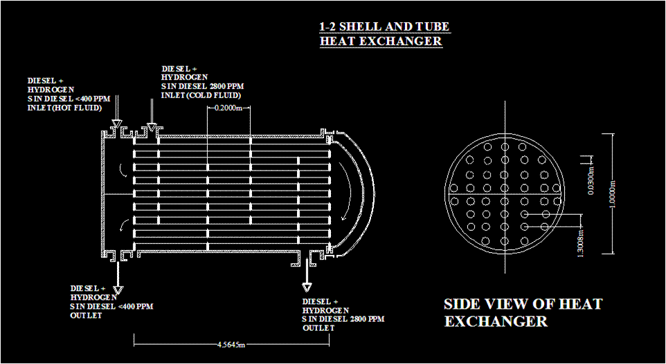
In a shell and tube heat exchanger, the ‘tube pitch’ is defined as the shortest center-to-center distance between adjacent tubes. There are different types of tube arrangement in a heat exchanger as triangular pitch, square pitch, diagonal square pitch, etc. in which triangular pitch arrangement facilitates the highest heat transfer rate than other arrangements. The width and depth of grooves in the tube sheet holes normally are 1/8 and 1/64 inch respectively. In a multipass shell and tube heat exchanger, the shell side crossflow area depends upon baffle spacing, clearance, and pitch. Shell side heat transfer coefficient in the case of the square pitch as compared to the triangular pitch under similar conditions of fluid flow and tube size is less. The minimum tube pitch recommended for shell and tube heat exchangers is about 1.25 times the outside diameter of the tube. 6.5mm is the minimum recommended ligament for square pitch arrangement in heat exchangers.
shell and tube heat exchanger baffles cross section CAD diagram
Baffle cross-section


Baffles are the interconnectors of the tubes and shell of the heat exchangers. The shell side fluid will pass through the direction depending on the baffle's arrangements. The rate of heat transfer also will depend on the baffles spacing. Different types of baffles are used as disk & ring, segmental, and orifice. A transverse baffle is a segmental baffle, disk-type baffle & helical type baffle, etc. The shell side pressure drop in a shell and tube heat exchanger is maximum for the orifice baffle. Forgiven the number of passes, pitch, and tube diameter, the maximum number of tubes that can be accommodated in a shell of tripled inside diameter will be considerably more than 9 times. Copper is the best tube material from a thermal conductivity point of view. In a heat exchanger, shell-side fluid velocity can be changed by changing the tube layout and pitch. Baffles are provided in a shell and tube heat exchanger to increase the turbulence and velocity of the shell side fluid. The minimum baffle spacing recommended in a shell and tube heat exchanger is equal to 5 cm or 0.2 times of shell diameter. In a multipass shell and tube heat exchanger, the baffles on the shell side are primarily provided for creating turbulence.
A plate and frame
heat exchanger


Design of a shell and tube heat exchanger

                       A minimum cleaning lane of 6.5 mm is provided when tubes are on a square pitch. Minimum tube sheet thickness (in which tubes are fixed) is equal to the O.D. of the tube up to 15mm tube diameter; and for > 15 mm tube diameter, the tube sheet thickness is smaller than tube diameter. O.D. of the tube is 6 to 40 mm while the tube lengths used are 0.5, 2.5, 3.0, 4.0, 5.0, and 6 meters. The average in the tubes of a 1- 4 heat exchanger is 4 Times that in a 1-1 heat exchanger having the same size & the number of tubes and operated at the same liquid flow rate. Tube side pressure drop in a 1-2 heat exchanger (for turbulent flow of fluids through the tubes) is about 1/4 times, that in a 1-1 heat exchanger having the same size & the number of tubes and operated at the same liquid flow rate.
                      The clearance between the shell & baffles and between the tube & baffles should be minimized to avoid by-passing of the fluid, but it should permit the removal of the tube bundle. Baffles are supported independently of the tubes by tie rods and positioned by spacers. Tie rods are fixed at one end of the tube sheet by making blind holes and the minimum number of tie rods is 4 with at least 10 mm diameter.
Design of shell and tube heat exchanger using CAD
     
In the case of a shell and tube heat exchanger, the minimum shell thickness for carbon steel (inclusive of corrosion allowance) depends on shell diameter and is in the range of 5 – 11mm. The ratio of tube length to shell diameter in the case of the liquid shell and tube heat exchanger ranges from 4 to 8. Steam is preferred to be used as a heating medium in heat exchangers, because of its high latent heat. The high specific heat of water makes it a widely used coolant in heat exchangers.

The ratio of tube length to shell diameter for a shell and tube heat exchanger is 4:1 to 8:1 for liquid-liquid exchangers and< 4:1 for gas-gas exchangers. In a shell and tube heat exchanger, the overall heat transfer coefficient is proportional to the tube side (volumetric flow rate)0.8. This is valid, only when the ratio of the tube side film resistance to the total resistance is almost equal to 1. In a multipass shell and tube heat exchanger, the problem of differential expansion between the shell and tube passes is taken care of by using a U-bend or floating head tube sheet.

For multipass shell and tube heat exchangers, when the flow is a mixed one that is co-current and countercurrent, the  LMTD correction factor is used. The various types of baffles used in the heat exchanger are
1. Segmental
2. Disc and doughnut
3. Orifice
Shell side pressure drop depends on
1. Mass velocity of shell side fluid
2. Baffle spacing
3. Shell diameter
4. Tube pitch and diameter
5. Density and viscosity of the shell side fluid.
In shell and tube heat exchangers the tubes are generally connected to the tube sheet by the following two methods
Tube rolling
Ferrule connection
Because of the abundance and high heat capacity, water is used as a coolant in heat exchange equipment.

The main disadvantages of concentric pipe heat exchangers are:
Comparatively less heating surface
Considerable space requirement
Prone to leakage
High maintenance cost
In normal practice, the outlet temperature of the water is not allowed to reach much higher than 50oC to avoid excessive corrosion. Because of the flexibility possible in baffle arrangements, an extremely large or small volume of fluids is best routed through the shell side of a shell and tube heat exchanger. The advantages of square-pitch arrangements over the triangular pitch in the case of heat exchanger tubes are:
1. Easily accessible for external cleaning
2. Low-pressure drop
The following characteristics of the fluid are to be considered while decreasing its route in the heat exchanger:
1. Viscosity
2. Fouling
3. Corrosiveness
4. Pressure.

Shell and Tube Heat Exchanger Calculator


Heat Duty (Q): kW
Hot Fluid Inlet Temperature (T1): °C
Hot Fluid Outlet Temperature (T2): °C
Cold Fluid Inlet Temperature (t1): °C
Cold Fluid Outlet Temperature (t2): °C
Hot Fluid Mass Flow Rate (m1): kg/s
Cold Fluid Mass Flow Rate (m2): kg/s
Tube Outer Diameter (D): m
Tube Inner Diameter (d): m
Tube Length (L): m
Hot Fluid Side Heat Transfer Coefficient (h1): W/m²°C
Cold Fluid Side Heat Transfer Coefficient (h2): W/m²°C
Overall Heat Transfer Coefficient (U): W/m²°C
Log Mean Temperature Difference (LMTD): °C
Heat Exchanger Area (A): m²
Number of Tubes (N): -
Baffle Spacing (B): m

Variation Of Fluid Temperatures In Heat Exchangers

CAD drawing of a heat exchanger
The Dance of Heat Transfer: Unlocking the Secrets of Heat Exchangers

In the world of thermal engineering, heat exchangers play a vital role in transferring heat from one fluid to another. This intricate process is governed by the fundamental principle of energy balance. By applying this principle, engineers can determine the temperatures of both hot and cold fluids at the inlet and outlet of the heat exchanger.

The Energy Balance Equation

The energy balance equation is a powerful tool that helps engineers calculate the heat transfer rates, fluid temperatures, and design parameters of the heat exchanger. By solving this equation, engineers can determine:

- The temperature of the hot fluid at the inlet and outlet
- The temperature of the cold fluid at the inlet and outlet
- The required heat transfer area
- The number of tubes
- The number of shell passes

Counter-Current Shell and Tube Heat Exchangers

One of the most common types of heat exchangers is the counter-current shell and tube heat exchanger. In this design, two streams pass over each other in opposite directions:

- The hot fluid enters the heat exchanger at a high temperature and flows through the tubes.
- The cold fluid enters the heat exchanger at a low temperature and flows through the shell.
- As the hot fluid flows through the tubes, it transfers heat to the cold fluid, causing its temperature to rise.
- The cooled hot fluid exits the heat exchanger at a lower temperature, while the heated cold fluid exits at a higher temperature.
The temperature difference between the terminal points of the heat exchanger is called an APPROACH and the temperature change obtained by an individual stream of fluid is called a RANGE. A point temperature difference is a local difference between the hot and cold fluids at a specified position of the heat exchanger which is Th - Tc. 

Q = mh cph (Th1 – Th2) = mc cpc (Tc2 – Tc1) 

Neglecting any loss of heat, the overall heat balance can be written from the law of conservation of energy, where heat supplied by the hot fluid is equal to heat observed by the cold fluid.
Subscripts h & c refer to hot and cold fluids;
1 & 2 are inlet and outlet respectively
m = mass flow rate, kg/s 
cp = specific heat, kJ/kg K


A required rate of heat transferred into a stream of fluid can be calculated by the above equation taking some assumption of the temperature availability of the streams.

Let W = m cp = kJ/sK = kW/K
Wh/Wc = (Tc2 – Tc1)/ (Th1 – Th2)
Information on the heat conduction process:
  • The flow of heat by conduction is the result of the transfer of vibrational energy from one molecule to another, the transfer of kinetic energy, and the movement of free energy.
  • Transfer of heat by conduction is generally formed from one part of a body to another part of the same body and between two bodies in physical contact.
  • When compared with non-metallic solids the metallic solids usually have much higher thermal conductivity.
  • Among the liquids, water has a comparatively high value of thermal conductivity which is due to partial ionization.
  • For gases, thermal conductivity value increases with an increase in temperature.
  • The Prandtl number for water varies from 5 to 10.
  • With the increase in concentration, the thermal conductivity of liquid generally decreases.
  • For conduction through a thicker-walled tube, the value of the mean radius used in the heat conduction equation is given by r2 – r1/ ln(r2/r1).
  • When a heat exchanger is used for condensing the vapor of the distillation column or any equipment, to maintain the constant temperature on the shell side of the heat exchanger only single component vapor should be allowed and its temperature should be below superheated temperature. At this condition for a constant pressure on the shell side, the constant temperature will be maintained. Consistent condensation of vapors is also achieved.