 |
Distillation Column |
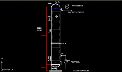
Simple CAD diagram of a distillation column can explain how to draw the column for a basic calculation of mechanical designing of the structure, it is a rough diagram to have a view of the plates, manhole, condenser, heat exchanger and supports to the column. you can modify this skeleton and have more complex accessories, by changing sieve plates and height and width of the column in your CAD software which suits your project design.
 |
CO2 and Ammonia stripper |
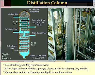
A schematic drawing of distillation column which is used to extract CO2 from NH3 from wastewater, bubble cap trays and low-pressure steam is used for stripping. An operating temperature is about 190 0 centigrade, operating pressure 3.5 kg/cm2. SS304L (stainless steel) is used as the material of construction. The dimensions are like 1600 mm inner diameter, 27200 mm tan to tan length, with 55 number bubble cap trays and 400 mm tray spacing.
A basic diagram of distillation column should represent the number of trays, types of trays, the location of plates and it weir and downcomers diameter and plate diameter, manholes locations, basement and its dimensions, inlet feed locations and distillate, reflux locations, reboiler types and vapor input. Distillation column diagrams differ from each mode of operation like continuous and batch.
In case of catalyst distillation placement of catalyst bed and the quantity of catalyst should be represented and the supporting trays diameter and thickness will add up the load to the distillation column. Load calculations are simulated based on the material of construction and design construction of the column will show the air swing of the column due to wind drag.